Posted on April 28, 2021 in Accuracy, Help, UAV LiDAR, and Vehicle LiDAR
Exploding the UAV LiDAR accuracy myths
There is a continual conversation across the UAV LiDAR community about accuracy, what it means and how important it really is. As with any technical question, this depends on what you want to achieve. Gert Riemersma, Founder, President and Chief Technical Officer at Routescene, explains the fundamentals of LiDAR accuracy and how to make sense of it all.
Getting to grips with accuracy
Accuracy can be defined as how close a measurement is to its real value. Normally accuracy is expressed as a range i.e. ± 2cm or as a standard deviation such as 3cm to 1σ (sigma) . To determine LiDAR accuracy you will need to take multiple sensor measurements to the same point, then compare those measurements to the real world. The real-world measurement is typically determined by using a much more accurate measurement technique.
Relative versus absolute accuracy
A distinction has to be made between relative accuracy and absolute accuracy. The one that is of most interest depends upon your application. For any survey you will always be able to determine relative accuracy, and if additionally, your survey data needs to be analyzed against other datasets then absolute accuracy will be required.
The relative accuracy of a sensor can, for example, be determined by comparing distances, such as the length of a roof in a 3D model, against the real world measurement of that roof, then computing the variance of all the measurements. This is typically done by plotting the results on a histogram.
Absolute accuracy is defined as the difference between the position of a point in a 3D model to its true real-world position. Absolute accuracy takes into consideration the coordinate system in use, the transformation parameters, and the errors present in the reference base station.
Understanding errors
It is common for surveyors to look at the errors in their measurements, with the aim to minimize these to create an accurate system. There are three types of errors:
- Gross errors – mistakes you make such as when measuring the height of a tripod (if you have remembered!)
- Systematic errors – constant errors due to a miscalibration of the INS, or a constant bias in the compass
- Random errors – noise in the measurements.
The fewer the number of errors and the smaller they are, the more accurate the system. When the Gross and Systematic errors are removed, by cross-checking your measurements, ensuring there are no mistakes in writing down setup information, and undertaking a robust and rigorous calibration of the sensor, then only random errors remain. As the word indicates, these errors are random and cannot be altered, and this provides the quantitative value for accuracy. These random errors are typically plotted on a histogram and the variance of the results (i.e. the distribution of the measurements) will provide the measure of accuracy and this is normally expressed in terms of the Standard Deviation or accuracy.
When the random errors (or noise) in a sensor is high then the only way to improve the accuracy of the system is to:
1. take repeat measurement and average the results – this is difficult to achieve in a LiDAR system as each point is unique due to the inherently dynamic nature of the measurement technique
2. use a different, higher quality LiDAR sensor with a lower noise level.
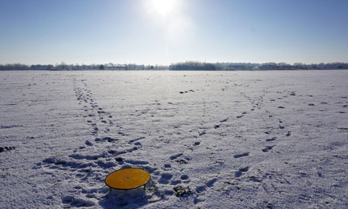
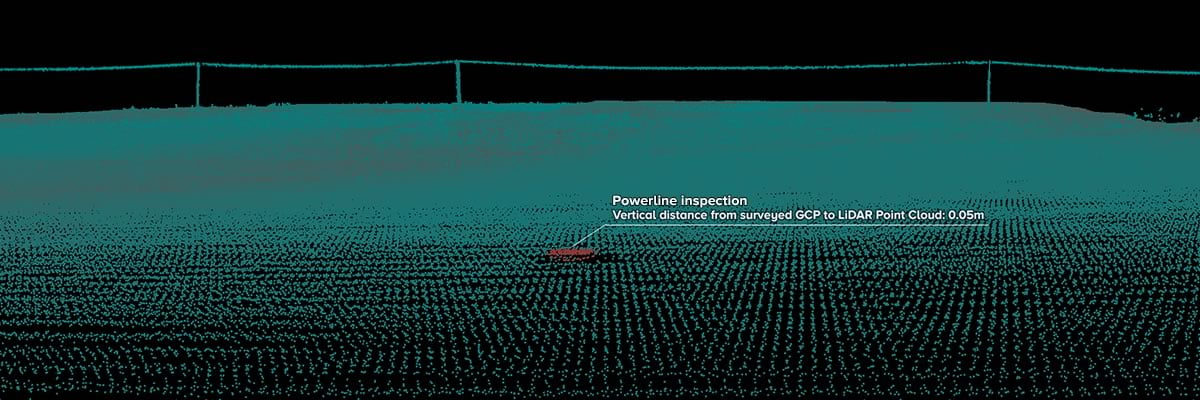
Drone LiDAR accuracy improved using Ground Control Targets from Routescene
Determining the accuracy of integrated LiDAR systems
There are many different components in a fully integrated LiDAR system and each has their own accuracy value, which is either expressed as a distance or as an angle. The LiDAR sensor has a range error; the GNSS has a horizontal and vertical position error; the INS has an angular roll, pitch, and heading error; the offsets to the GNSS antennas have a distance error, and the LiDAR sensor relative to the INS has an angular offset error. In the case of the latter this relative angular “systematic” error can be minimized through undertaking a thorough calibration prior to or during the survey.
Beware!
The angular error of the INS adds complexity to the whole accuracy discussion as it increases with range. So in the case of an integrated LiDAR system, the accuracy will degrade the further an object is from the sensor. It is therefore important to understand when you review the accuracy figure of an integrated LiDAR system to know at which range this accuracy figure has been derived. This is not always made clear by integrated LiDAR system manufacturers.
To determine the overall accuracy of the LiDAR system the following simplified formula should be used to account for all the individual component accuracies. There are a few minor errors inherent in the system that are not documented here, they are very specific and beyond the scope of this article.
Overall accuracy = √ [ (GNSS error)2 + (LiDAR range error)2 + (range * tan (INS error))2 + (range * tan (LiDAR – INS error))2 ]
Remember that accuracy costs
It cannot be disputed that the higher the accuracy, the better the results you can achieve, the more impressed your client will be, and the more work you will get from them. Alas, this is the ideal world. As with everything else in life, compromises have to be made. High accuracy requires high-quality components such as the internal laser diodes, microchips, as well as complex software algorithms and high manufacturing standards. And high quality is expensive. The quality is ultimately reflected in the end-user price of the integrated LiDAR system.
Higher quality components are typically also much heavier. For drone-based LiDAR applications, this translates to shorter flight times and lower productivity, which has a cost associated with it as well.
In the design stage of developing an integrated LiDAR system compromises have to be made, to achieve a balance between cost and performance to ensure that the final product is “fit for purpose”. This design stage is critical and requires great insight, in-depth knowledge, and user experience to understand the levels of accuracy and weight acceptable to the end customer.
Routescene® smart thinking = higher LiDAR accuracy
We’ve applied smart thinking to work out where the most cost-effective accuracy gains could be made to develop Routescene’s® UAV LiDAR Systems, which includes:
- We’ve considered the specification of the LiDAR sensor used. For example, a Velodyne HDL32 is at least twice as accurate as a Velodyne VLP16. This is due to the superior quality laser diodes used in the HDL32
- Choosing the perfect blend of sensors, which involves considering the accuracy of each. For example, using a low-grade LiDAR with a high-grade INS is ineffective and poor value for money. This is because the noise of a low cost LiDAR sensor negates any of the potential accuracy gains that could be made by integrating an expensive, high accuracy INS
- Providing a dual antenna heading solution to ensure an accurate and stable heading reference. This provides up to 10 times improvement relative to a single GNSS solution, which relies on a combination of a gyro and \ or magnetic compass to provide heading
- Providing the ability to improve the level of accuracy as and when required. Routescene purposefully chose GNSS/INS products that enables you to post-process the drone trajectory to improve the accuracy by up to a factor of 4.
The Routescene® UAV LiDAR integrated solutions are designed with the end-user in mind. From our own field experience, we understand the levels of drone LiDAR accuracy required across a wide range of different customers and applications. We’ve engineered a range of solutions, having considered where we can make sensible compromises across the hardware components, resulting in “fit for purpose” integrated systems to deliver the best results most cost effectively.
Hardware performance is only one half of the story. We’ve dedicated our energies into continually developing our software, workflows, and procedures, so you can enjoy additional accuracy gains from infield calibrations to refine data collection to specific post-processing tools.
Routescene is all about continuous improvement. We constantly undertake Research & Development to achieve a deeper understanding of the errors inherent in all LiDAR systems. With this understanding we strive to minimize errors through improvements in hardware, firmware and software. The end game – to produce more accurate systems to ultimately provide you with even better results.