Posted on January 10, 2021 in Categories
Developing Quality Control & Quality Assurance for UAV LiDAR
The survey and mapping industry has experienced phenomenal growth with the number of surveys conducted using UAV LiDAR continuing to increase. The impact of this disruptive technology is similar to that seen in the 1980’s when GPS (Global Positioning System) was first introduced and applied to high accuracy surveying and positioning. In both cases, Quality Assurance and Quality Control (QA/QC) procedures have lagged behind the curve. It takes a while for users to understand the importance of, adopt and implement a QA/QC methodology applicable to each new technology. Typically QA/QC is implemented after the initial flush of excitement has dissipated and the technology is being used in earnest.
Learning QA/QC lessons from the oil industry
QA\QC is essential to ensure the data delivered to the end customer is as accurate as possible and the level of accuracy can be proven. In the 1980’s oil rigs were positioned without any quality checks resulting in millions of dollars wasted. My father, the chief surveyor for Royal Dutch Shell (1977–1987), gleefully regaled a story of how a competitive oil company positioned and then proceeded to drill for oil very close to Shell’s concession in Borneo. When they found oil, my father proceeded to prove that they had actually positioned their oil rig within Shell’s patch and thanked them for their efforts in finding new oil reserves for Shell. The lack of Quality Control had cost the competitive oil company dearly.
In his time as Chief Surveyor he insisted that contractors adopted QA/QC methodology. He overcame their objections on the grounds of cost, the need to collect additional data and the extra time required to process results. These objections are now completely eradicated in the oil & gas survey industry. It is now taken as read that you will demonstrate the reliability of the data collected and you have the utmost confidence in it. As a direct result of these QA/QC processes being adopted many opportunities arose with new companies formed and new software developed to cater for the demand.
Ethos of Quality Assurance
Routescene has a strong ethos of Quality Assurance including a robust survey and data processing methodology. Applying consistent and disciplined procedures improves results and enables you to identify any errors early. Drawing on my own foundations in land surveying, my many years of experience working in the offshore industry and my father’s QA/QC mantra, a rigorous QA methodology has been applied across the design and development of Routescene’s systems since inception, the first product launch in 2014 and continued improvements and new products to date.
Establish ground control
Since day 1 we have always considered how the level of accuracy required will impact flight planning, undertaking real-time QC monitoring during the actual survey, checking the results on-site immediately after each flight and deploying Ground Control Targets to provide an independent check of the results. We advocate that every UAV LiDAR survey has ground control established. Setting Ground Control Points (GCP) helps to demonstrate a certain level of accuracy has been achieved. This also avoids data processing issues and assists with the calibration of the sensors on the drone: all of which improve the confidence in the accuracy of the survey.
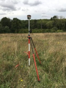
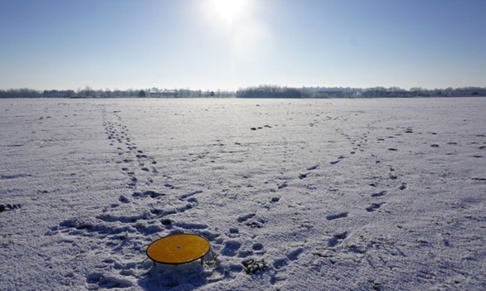
Surveying in a Ground Control Point using a RTK GNSS Rover, Norfolk, UK
UAV LiDAR Ground Control Targets
Unlike photogrammetry, it is very difficult to identify individual features such as the corner point of a building, in a LiDAR point cloud. In an orthophoto the detail is continuous with each pixel joining onto it’s neighbors. In a LiDAR point cloud the points are discrete with a space between each individual point. This poses a real challenge if the feature you require is in between two points. To remedy this and enable calibration and accuracy analysis to be performed it is typical in LiDAR surveys to select a flat surface and analyze each axis individually, which is mathematically far more robust. However, in practice finding a flat surface in a highly vegetated undulating terrain is a tricky task. The solution… utilize dedicated Ground Control Targets during a LiDAR survey to enable ground control.
At Routescene we have evolved the design of our Ground Control Targets over the years, experimenting with a variety of different designs, materials and methodologies. The resulting Ground Control Points can be easily consumed in our post-processing software, Purepoint, which automatically generates Quality Assurance Reports. We are the only manufacturer offering Ground Control Targets specifically designed for UAV LiDAR mapping.
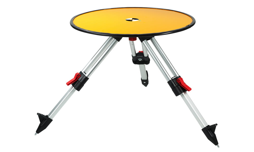
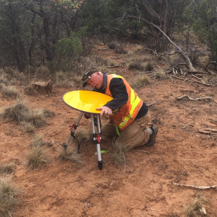
Routescene LiDAR Ground Control Target
Quality Assurance procedures
The required accuracy of a topographic survey will be determined prior to commissioning or undertaking the survey and this will vary depending on the use and possibly the National Standards that the data needs to comply with. Read further details about the importance of accuracy in our article UAV LiDAR accuracy.
Irrespective of how the data is collected and then processed the means by which you QA\QC the data needs to be considered. There are existing standards you can use, notably from ASPRS, which offer numerous Accuracy Standards and guidelines for both photogrammetry and LiDAR. What is common to both these survey techniques is the need to use physical Ground Control Points, dispersed across the survey area, to firstly provide a means to calibrate the sensor and secondly to check that the desired accuracy has been achieved.
We consider the latest trend to use an orthophoto, derived from a UAV photogrammetry survey, to calibrate and control a UAV LiDAR survey to be fundamentally flawed. The gross assumption is that the orthophoto is perfect and this is certainly not the case as its position and accuracy are derived from GCP’s. The practice is inconsistent with good survey practice as it introduces additional errors into the QA process. It is prudent to “cut out the middleman”, remove the orthophoto from the process, and directly utilize the original GCPs in the QA process.
Surveying in a Ground Control Point using a RTK GNSS Rover, Norfolk, UK
How to use UAV LiDAR Ground Control Targets
Routescene’s Ground Control Targets are large discs to be positioned on the ground within your survey area. Placed on known geographical points, called Ground Control Points, the coordinate of each Ground Control Target is established using an accurate and independent survey technique. Typically this will be undertaken using an RTK GNSS Rover using a Virtual Reference Station (VRS). The number of Ground Control Targets to be deployed depends on the size of the survey area: for a 500 x 500m area we recommend, 4-8 targets are used for the boresight calibration and as checkpoints.
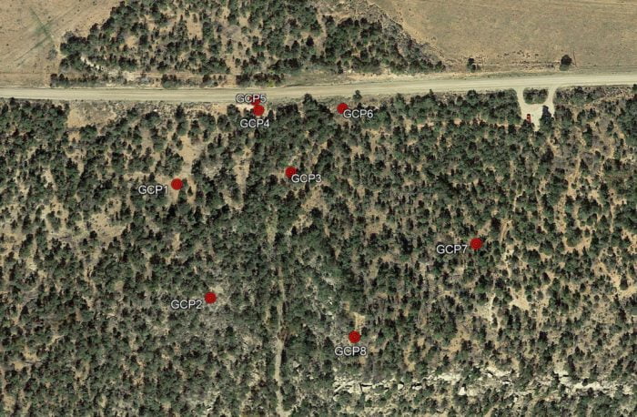
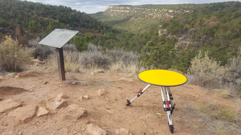
Distribution of Ground Control Points at a project in Sand Canyon, Colorado, USA
Measure accuracy with a high degree of confidence
The Ground Control Targets can be seen in the resulting geo-referenced point cloud so you can directly compare the known coordinate of the physical Target with that visible in the point cloud. The difference between the two coordinates is the error: confirming the level of accuracy achieved in the survey. The benefit of collecting many hundreds of points per square meter during a LiDAR survey can be leveraged in the error analysis to create robust statistics and provide a measure of accuracy with a high degree of confidence. Routescene’s Targets are 60cm in diameter and typically each Target will be hit 200-300 times by the lasers from the LiDAR system.
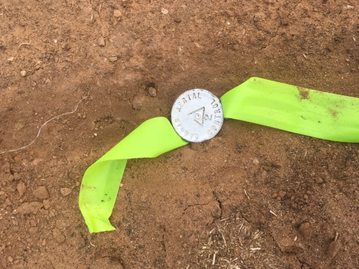
The target is plumbed directly on top of the GCP and the height offset between the GCP and the target recorded. The Z difference between the known target height and the LiDAR point can then be calculated and used to generate a histogram. The Standard Deviation and the Root Mean Square Error (RMSE) can be computed with confidence given the large number of observations in the sample. A similar process is followed to compute the X and Y errors.
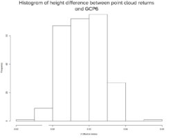
Histogram showing the Z difference between the Ground Control Target’s known height and that derived from the LiDAR point cloud. 0.01m spacing, 250 hits. Sand Canyon project, Colorado, USA.
This error analysis forms the basis of the Quality Assurance Report. We have automated this process by automatically extracting the location of each Target from the point cloud and then comparing the target’s “points” with the imported GCP coordinate.
Routescene LiDAR Ground Control Target v2.0 – used during a fixed wing UAV survey in Germany
Highly retro-reflective targets
Through continuous improvement, based on our own field experience and customer feedback, our LiDAR Ground Control Target design is in its fourth iteration. 60cm in diameter, mounted on a small tripod, and covered in a highly retro-reflective material, the Target gives a high-intensity return and is easily identifiable in the resultant point cloud.
We use a retro-reflective material so that we can make the points stand out from the background vegetation. Background vegetation has a similar (high) reflectivity to white material so we need something better to enable it to stand out and allow us to automatically extract the target from the point cloud. The biggest struggle we have had in the past is ensuring that we don’t accidentally classify high grass as being part of the Ground Control Target. Raising targets from the ground has also allowed them to be identified easily and classified using automatic filtering. The extracted point cloud is then used to create a QA report and to also undertake an automated Boresight alignment.
We find that the retroreflective targets give a more uniform intensity return (compared to white painted targets) which is helpful in the automated classification. The intensity of the return of painted targets will vary significantly the further away you fly from the target, the best intensity return being achieved when you fly directly over it. In the case of retro-reflective targets the intensity of the return tends to remain more uniform regardless how far you fly from it.
Each target has a bubble level built into the surface so it can be accurately leveled. The target is raised from the ground using the tripod, again to enable easy identification, so the returns can be automatically extracted from the point cloud.
We have also found the Routescene Ground Control Targets to be robust and wind-resistant, meaning that once they are positioned they stay in position. Thus reducing time having to inspect and reposition targets during the survey.
The automatic extraction and analysis are undertaken in Purepoint using the QA Reporting filter. There are many other filter tools in the software enabling workflow to be streamlined.
Ground Control Targets deployed during Sand Canyon survey in Colorado, USA
Boresight calibration
System calibration, part of the QA process, is used to both estimate the systematic errors in the Routescene LidarPod equipment and to determine the boresight alignment. Routescene’s operational procedures recommend that a boresight alignment is performed during every project. We identified that over time there tends to be slight variations in the boresight alignment parameters, and as such they cannot be assumed to be constant. Variations in operational temperature, repositioning of the antenna poles, GNSS/INS Kalman filter alignment all contribute to these slight variations.
Routescene’s Ground Control Targets are used to perform this system calibration. The Targets are positioned in a particular way to determine the roll, pitch and heading misalignment. The UAV overflies the Targets in a specific pattern and in subsequent post-processing, the boresight misalignments are computed and applied to the raw point cloud.
Conclusion
Deploying Ground Control Targets on known and accurately coordinated GCPs prior to a UAV LiDAR survey provides the assurance that the survey has been properly executed. The final survey results are more robust and quantifiable and it can be demonstrated that the client specified level of accuracy is achieved. Ground Control Targets can also be used to calibrate the equipment on every project, again ensuring the best possible accuracy is accomplished. In addition, adopting Ground Control Targets in a survey simplifies post-processing, enabling any gross errors to be identified early in the processing pipeline and avoiding costly reprocessing.
For excellent UAV LiDAR results you need to undertake Quality Assurance. Routescene provides this as standard. Investing in Ground Control Targets for UAV LiDAR surveys increases the value of your data. Taking that extra time and effort to install Targets and to generate Quality Assurance Reports will improve the quality of and your confidence in the resultant data.
About the Author

Gert Riemersma trained as a land surveyor and worked as a hydrographic surveyor for 20 years before moving to work with LiDAR and developing the Routescene UAV LiDAR solution in 2014. His experience includes working as a navigator on an aeromagnetic survey in 1985, flying 16-hour sorties halfway across the Atlantic in a DC4 with very limited GPS constellation supplemented with Loran-C to navigate by. Routescene designs and manufactures UAV LiDAR Systems and Purepoint software. Routescene’s customers have used our systems all over the world, from Australia to Alaska, across a variety of different projects.
Footnote
Quality Assurance – the process of you demonstrating that the reliability and accuracy of the data you have collected is to the agreed specifications.
Quality Control – the process that an end client will use to inspect and check that the collected data is to the standard as agreed in the specifications.