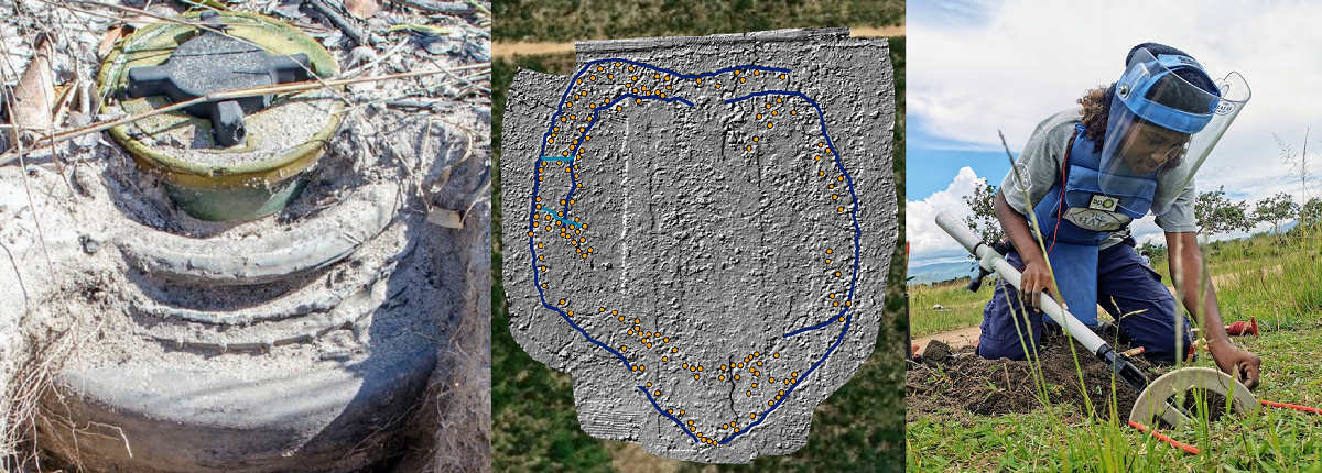
We are extremely proud of this new case study which discusses the collaboration between Routescene and The HALO Trust to determine the effectiveness of UAV LiDAR to improve land mine clearance planning in wartorn countries. The project has taken 3 years to complete, starting with a feasibility test in Scotland in 2020 followed by Routescene’s hardware and software being used across three heavily mined sites in Angola between 2021-2023.
![]()
![]()
This project proved that UAV mounted LiDAR systems can be used to detect battlefield features which can be indicators of minelaying. The results were used to target future surveys and clearance operations in Angola hence making clearance efforts safer and quicker.
The magnitude of the problem
At least 60 states and territories around the world are contaminated by land mines. Some of these, such as Angola, Afghanistan, and Sri Lanka, are suffering from the legacy of past and recent conflicts, while in Ukraine and other areas landmines continue to be laid [1]. Land mines kill or injure more than 5,000 people annually [1]. Mine clearance is a laboriously slow and expensive process and there is an obvious need to accelerate land mine clearance across the world.
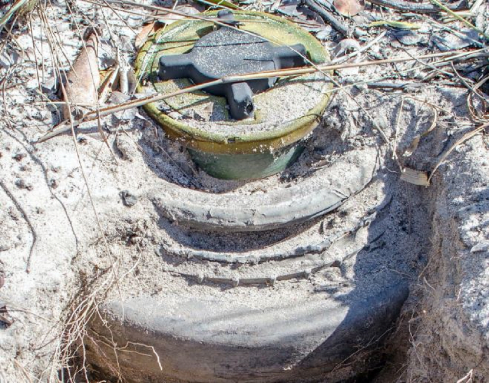
Figure 1: Anti-Personnel mine laid on top of an Anti-Vehicle mine in Angola.
As far as we are aware this is the first time that drone LiDAR has been used to identify battlefield features in Angola to aid clearance efforts.
The Angolan civil war
Fought from 1975 until 2002, throughout the Angolan civil war there was extensive mine laying by both sides. Cuando Cubango (Figure 2) saw some of the heaviest fighting and the Battle of Cuito Cuanavale was the largest conflict of the war. This area hosts some of Angola’s longest minefields. The mixed threat mine belts of Anti-Vehicle (AV) and Anti-Personnel (AP) mines continue to pose a deadly threat to the local community today.
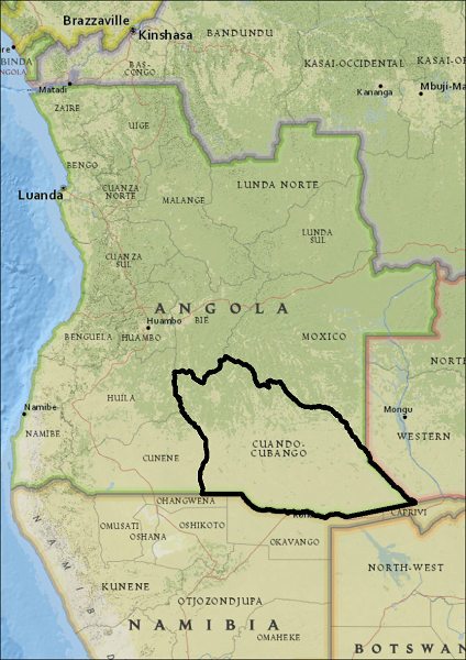
Figure 2: Cuito Cuanavale is in the province of Cuando Cubango, Angola.
The Routescene and The HALO Trust collaboration
The HALO Trust, the British mine-clearance charity, partnered with Routescene, an established drone LiDAR system and software manufacturer to undertake this case study.
The HALO Trust began clearance operations in Cuito Cuanavale in 2005. To assist the identification of unexploded ordnance (UXO) the charity more recently trialled drone remote sensing techniques including thermal infrared (TIR) and RGB cameras. Unfortunately due to the passage of time the battlefields are now overgrown with vegetation so the UXO and indicators of conflict which suggest the presence of AV and AP mines are no longer visible from the ground or the air using UAV mounted RGB or TIR sensors.
UAV LIDAR’s distinct ability to penetrate vegetation enabled The HALO Trust to map trench extents and features such as bunkers and craters to predict where a mine line may be located. In areas with large gaps in the mine lines or presenting a sharp change in direction, the UAV LiDAR data was analyzed to locate craters from mine detonations, often caused by animal accidents and wildfires, to inform the location of the mine line.
Feasibility project in Scotland in 2020
Routescene and The HALO Trust are both headquartered in Scotland. Before embarking on an expensive mission to Angola the teams performed a test locally in Scotland to confirm that Routescene’s UAV LiDAR System (Figure 3) could effectively map battlefield remains which could be identified in LidarViewer Pro, Routescene’s post-processing software.
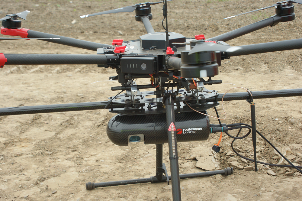
Figure 3: Routescene’s UAV LiDAR System used in feasibility project in Scotland.
A suitably vegetated site was found and a replica crater was dug to represent the conditions found in Angola (Figure 4).
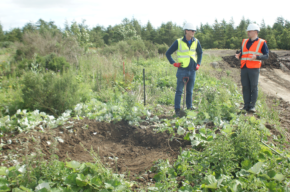
Figure 4: Imitation land mine crater created at Scottish test site.
The simulated crater was easily identified in the resultant Digital Terrain Model (DTM) (Figure 5) validating that UAV LiDAR would be capable of locating and mapping battlefield remains in Cuito Cuanavale, Angola.
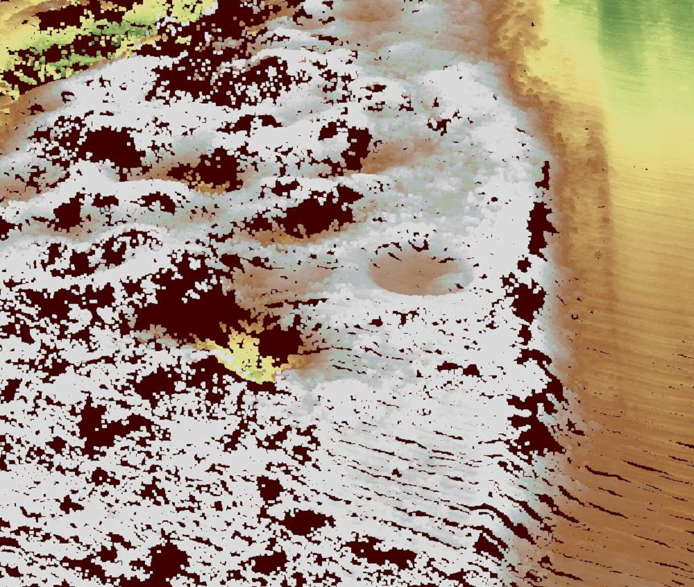
Figure 5: Point cloud, stripped of vegetation, showing the simulated land mine crater.
Equipment and software
Routescene constructed a demonstration UAV LiDAR System for this project (Figure 6). The unit contained a 16 channel LiDAR sensor, capable of collecting approximately 600,000 points per second, a GNSS/INS sensor and data storage to capture 12 hours of data. The system was designed to be resistant to in-flight vibrations and handling by users, and did not require a mobile or internet connection to operate, thus providing operational autonomy and data security. GNSS data was collected for the post processing of the trajectory to ensure the data was as accurate as possible.
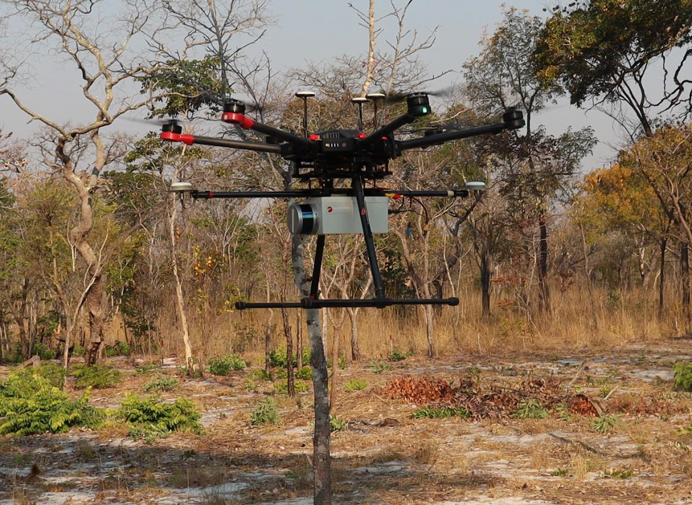
Figure 6: Routescene demonstration UAV LiDAR System mounted underneath DJI M600 Pro in Angola.
Routescene’s LidarViewer Pro software was used to post process the raw LiDAR datasets and export DTMs from each of the sites for analysis in ArcGIS Pro.
Survey sites in Angola
Three sites with known or suspected battlefield features were identified around Cuito Cuanavale as suitable locations for the project:
Site A: an abandoned military base outside of Longa village, approximately 100km North West of Cuito Cuanavale.
Site B: an extensive defensive mine line with an associated trench, approximately 9km East of Cuito Cuanavale.
Site C: an abandoned military base, approximately 25km South East of Cuito Cuanavale with evidence of AP mine laying within the base and at least one known trench and a suspected second trench.
Elevation: The terrain across the three sites was similar, all being relatively flat.
Vegetation coverage: Varied considerably: Sites A and C had dense tree coverage whereas Site B had light tree and shrub coverage.
Expected features: The battlefield features expected to be detected in the UAV LiDAR data were main trenches, communication trenches, foxholes (one man defensive positions), shell scrapes (shallow excavations allowing soldiers to shield from shell bursts and small arms fire) and craters from detonations.
Data collection
Sites A and B were surveyed during the dry season (August 2021) when vegetation cover was at its lowest. LiDAR data was collected from 40m above ground level (AGL) with one day of collection for each site. Site C was surveyed during the rainy season (April 2022) when vegetation cover was at its highest. Due to the size of the area and time limitations, Site C data was collected at 50m AGL over three days.
Practical challenges included locating suitable drone take-off and landing sites and difficulties siting the base station. At Sites A and B breach lanes and cleared land were available near the areas of interest however Site C was surrounded by uncleared terrain containing mines which posed a threat to life to the survey team. Instead the cleared narrow sandy roads were used and the equipment needed to be moved to let vehicles past (Figure 7). This also meant the flight time to the survey site was longer which reduced the volume of data collected per flight.
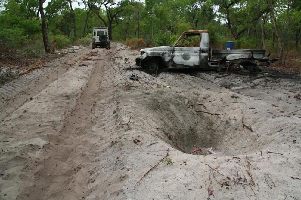
Figure 7: The survey team were restricted to using cleared narrow roads for setting up their survey equipment.
Results
The DTMs created from the LiDAR data provided a wealth of information across all three locations which could not be captured by other survey techniques. Defensive main trenches, Communication trenches, foxholes, shell scrapes and other crater-like features were clearly identified to enable the clearance team to plan their activities in a very targetted way.
Site A results
Satellite imagery at Site A (Figure 8) showed little evidence of the historical military base:
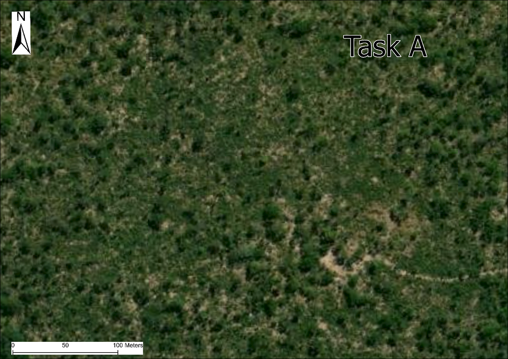
Figure 8: RGB satellite imagery at Site A showing no evidence of craters or trenches. Sources: Esri, DigitalGlobe, GeoEye, i-cubed, USDA FSA, USGS, AEX, Getmapping, Aerogrid, IGN, IGP, swisstopo, and the GIS User Community.
However when the UAV LiDAR data was overlaid onto satellite imagery multiple features became apparent:
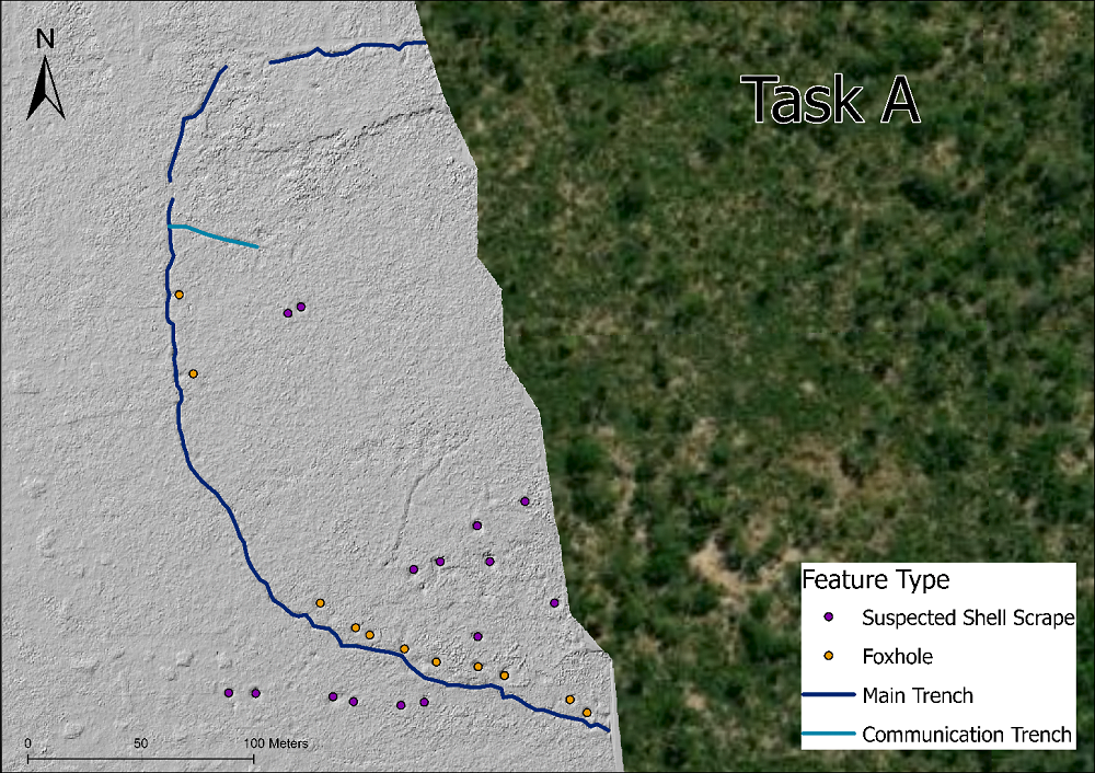
Figure 9: DTM showing predominant battlefield feature types at Site A. Sources: Esri, DigitalGlobe, GeoEye, i-cubed, USDA FSA, USGS, AEX, Getmapping, Aerogrid, IGN, IGP, swisstopo, and the GIS User Community.
The predominant feature was the defensive Main Trench around the former base with a Communications Trench branching off the north western internal side of the main trench (Figure 9). In total 40m of communication trenches and 496m of main trench were identified.
An additional 24 feature points were identified concentrated in the southern area of the dataset:
- 10 foxholes follow the inside of the main trench line, dug as part of the defensive positions around the base.
- 9 crater-like features clustered inside the southern area of the base with two further north closer to the communications trench and these are suspected shell scrapes.
- A line of 6 crater-like features outside the southern area of the main trench. It is unlikely to be AV mines as none were found at this location and again these may be evidence of shell scrapes.
The average depth and width of the foxholes (0.58m and 2.36m respectively) and the suspected shell scrapes (0.77m and 2.38m respectively) were similar at this site, which initially suggested these were the same feature. However, due to the suspected shell scrapes not being in the typical location and pattern of foxholes they were identified as a separate feature.
Ground truthing was undertaken where accessibility and vegetation coverage allowed to confirm the feature types identified in the dataset (Figure 10).
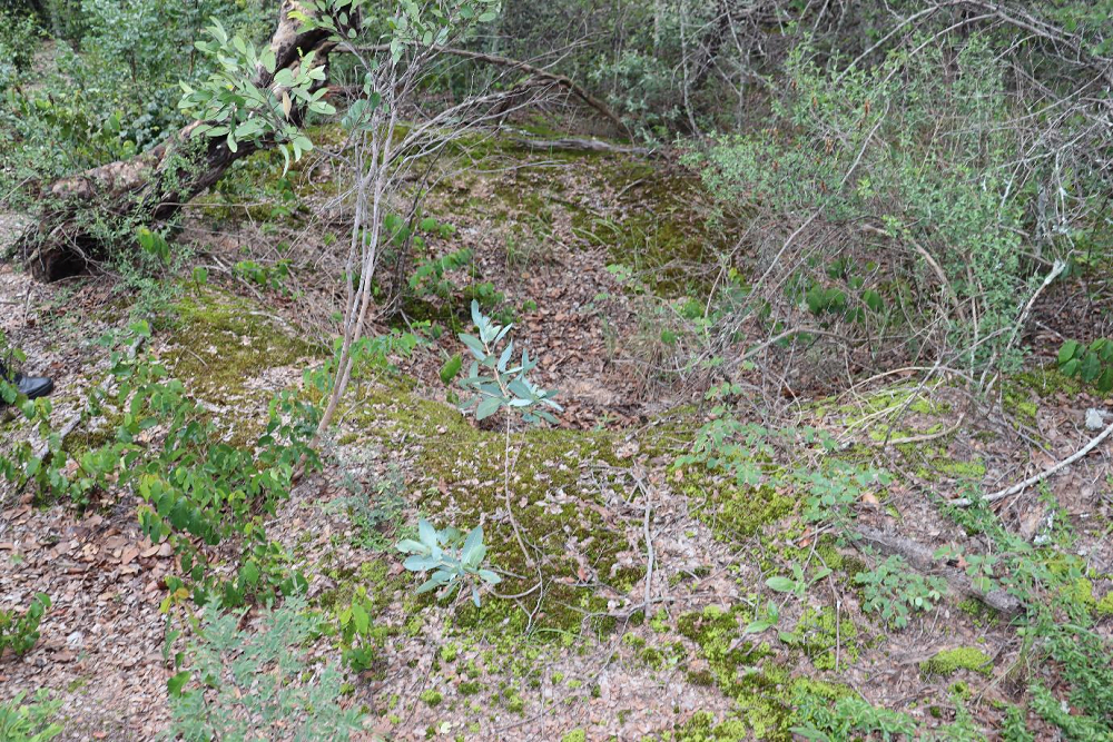
Figure 10: Example of a trench covered by vegetation at Site A.
Site B results
Site B had a lighter vegetation coverage than Site A which allowed some evidence of the main trench remains to be seen in the satellite imagery but other features were not visible (Figure 11):
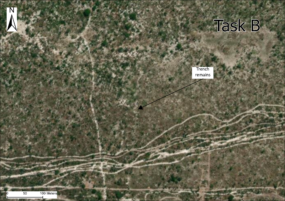
Figure 11: RGB satellite imagery at Site B. Sources: Esri, DigitalGlobe, GeoEye, i-cubed, USDA FSA, USGS, AEX, Getmapping, Aerogrid, IGN, IGP, swisstopo, and the GIS User Community.
However during field visits the vegetation coverage and lack of safe access impeded visual confirmation of what remained of the trench system (Figure 12):
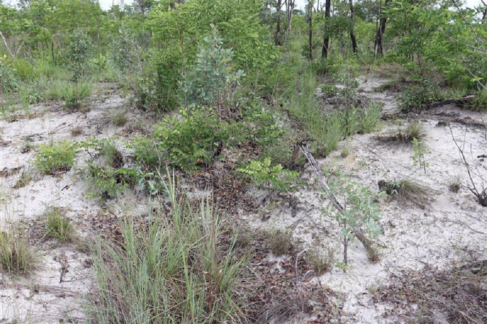
Figure 12: Example of the historic trench line at Site B with vegetation overgrowth which reduced visibility.
Analysis of the UAV LiDAR data identified multiple features that could not be seen in the satellite imagery, including a larger extent of the main trench, communication trenches, foxholes and suspected craters (Figure 13).
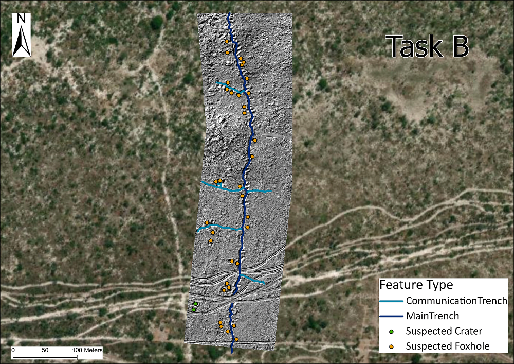
Figure 13: DTM showing predominant battlefield feature types at Site B. Sources: Esri, DigitalGlobe, GeoEye, i-cubed, USDA FSA, USGS, AEX, Getmapping, Aerogrid, IGN, IGP, swisstopo, and the GIS User Community.
In total the team identified:
- 500m of main trench and 281m of communication trenches.
- 34 foxholes.
- 2 suspected craters possibily from exploded ordnance but unlikely to be from AV mines as the mine line is to the east of the trench. As they were located in an uncleared area it was not possible to confirm the exact nature of these features.
- The suspected craters averaged 5.85m in width and 0.65m in depth, the foxholes averaged 0.67m in depth and 2.54m in width.
- Whilst the majority of the tracks were visible in satellite imagery the UAV LiDAR data revealed additional historical tracks. This information was used to identify locations of possible safe access roads to the site.
Site C results
This site was covered in dense vegetation which meant it was not possible to identify the locations of the suspected battlefield features either from satellite imagery (Figure 14) or from the ground (Figure 15):
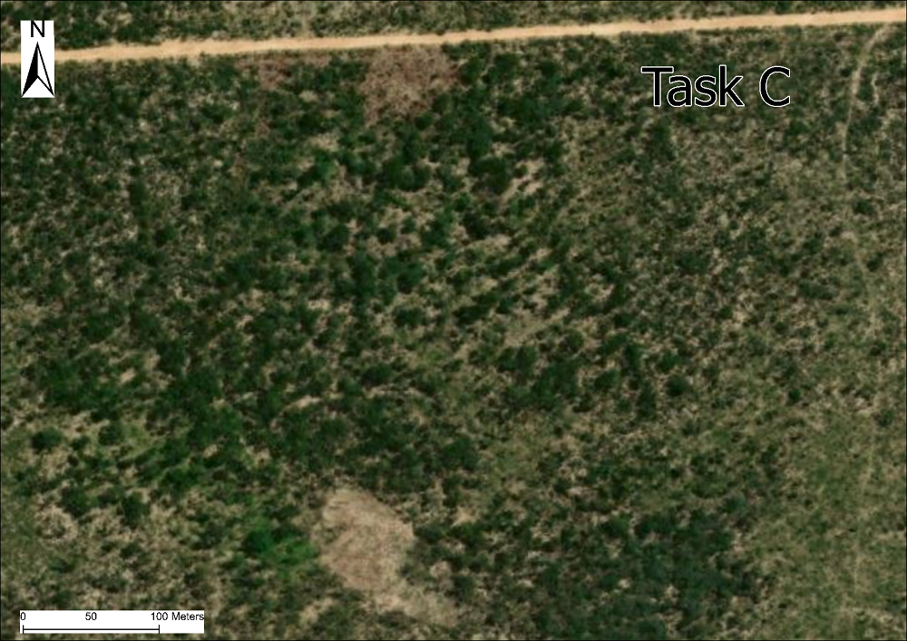
Figure 14: RGB satellite imagery at Site C. Sources: Esri, DigitalGlobe, GeoEye, i-cubed, USDA FSA, USGS, AEX, Getmapping, Aerogrid, IGN, IGP, swisstopo, and the GIS User Community.
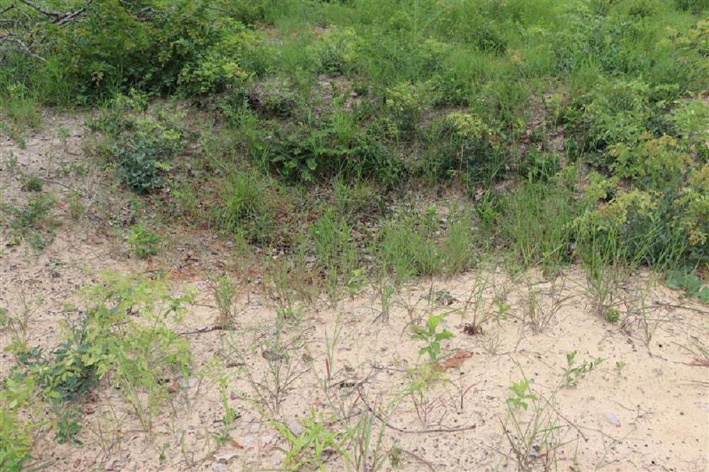
Figure 15: Example of a foxhole covered with vegetation at Site C.
Site C was suspected to have at least a single trench and multiple foxholes surrounding the previous military base. The UAV LiDAR data showed evidence of:
- 2 trench systems surrounding the former base as well as communication trenches (Figure 16).
- 157 crater-like features which follow both trench lines, believed to be foxholes due to their regular spacing in close proximity to the trench lines.
- Gaps in the trench systems which could be explained by the infill of soil over time levelling out the ground within the trench or rainwater lying within the trench preventing the LiDAR pulses from reaching the bottom of the trench.
- A circular inner trench system. Although the trench data was incomplete there was a continuation of the foxholes in the southern region between the two extents of the inner trench suggesting that the trench once continued to create an inner trench.
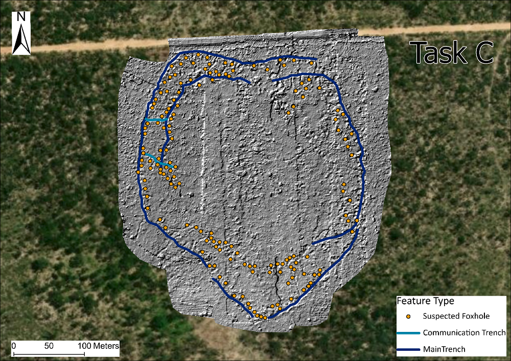
Figure 16: DTM showing predominant battlefield feature types at Site C. Sources: Esri, DigitalGlobe, GeoEye, i-cubed, USDA FSA, USGS, AEX, Getmapping, Aerogrid, IGN, IGP, swisstopo, and the GIS User Community.
Overall, 1429m of main trench (828m on the outer trench and 601m of inner trench), 73m of communication trench and 157 foxholes were identified at this site. The foxholes averaged 0.80m in depth and 2.81 in width.
Conclusion
This case study proved that UAV LiDAR systems and software can be used to detect and map battlefield features which can be indicators of minelaying. The UAV LiDAR data provided evidence of trenches, craters and foxholes at all the sites surveyed, features which were either not detectable or only partially visible in satellite imagery or during field visits. Remote sensing is not a replacement for but is complimentary to conventional minefield survey techniques. This work demonstrated how valuable drone LiDAR data can be to provide evidence that is not obtainable by other means, offering advantages over RGB and TIR imagery when looking for battlefield features hidden by vegetation.
The UAV LiDAR outputs, combined with contextual knowledge on the ground, provided valuable information to The HALO Trust’s mine clearance operations in Angola and supplemented conventional survey operations. The results informed clearance planning, made clearance efforts safer and expedited clearance through a targeted approach. The data will continue to be used to target future surveys and clearance operations.
Publication
The following journals and associations have kindly published articles on this project:
LiDAR Magazine (Nov/ Dec 2023, Volume 13 Issue 4)
Title: UAV-Lidar improves landmine clearance planning
ARPAS-UK – The UK Drone Association (November 2023)
Title: UAV LiDAR improves land mine clearance planning
“A day in the life of…” article explaining the work of Pedro Pacheco, a GIS Officer and Drone Pilot at The HALO Trust, the conditions they operate in and the challenges they face. Routescene is a member of ARPAS-UK.
LiDAR Magazine (October 2023, Volume 13 Issue 3)
Title: UAV-Lidar improves landmine clearance planning
GeoConnexion International (Autumn 2023, Volume 22, Issue 3) and on GeoConnexion website
Title: How to clear mines using UAV LiDAR
Discusses the practical challenges and technology needed to use UAVs to plan land mine clearance.
GIM International e-magazine (Issue 6 2023 Volume 37) and on GIM International website
Title: How UAV Lidar improves landmine clearance planning
Case study demonstrates the benefits of UAV Lidar to detect and map minefield features to inform clearance planning.
The Journal of Conventional Weapons Destruction (Issue 27.2 | Summer 2023) published by Center for International Stabilization and Recovery (CISR)
Title: How UAV Lidar Imaging can locate and map minefield features
Acknowledgements from The HALO Trust
We would particularly like to thank an anonymous private donor for their extremely generous support for HALO’s UAV trials in Angola and their commitment to innovation in mine action. This project would not have been possible without their help. We would like to thank Routescene for providing the UAV LiDAR system, software, training and ongoing support since 2020. This has included a demonstration project, technical and data processing support. In addition, we would like to thank Claire Lovelace and Siân McGee from The HALO Trust Angola programme for their ongoing support in the field and for supporting with the analysis of data.”
About the authors
Gert Riemersma, Chief Technical Officer, Routescene
Gert Riemersma is the founder, president, and Chief Technical Officer at Routescene. A technical innovator with over thirty-five years international survey and business experience, he has been working with LiDAR since 2008 and with UAV LiDAR since 2013. He specializes in the development of survey and mapping systems and software, converting technically challenging problems into practical products. A qualified Land & Hydrographic Surveyor, Gert has many years of survey and hydrographic experience gained in a variety of different environments and locations around the world.
Katherine James, Remote Sensing Specialist, The HALO Trust
Katherine James is a Remote Sensing Specialist working with The HALO Trust (HALO). She specializes in the use of UAVs for assisting in the removal of landmines and other unexploded ordnance in countries and territories that have been affected by conflict. Additionally, she is responsible for implementing the deployment of small drones for supporting non-technical survey for HALO globally. Katherine holds a bachelor’s degree in geography from Aberystwyth University and a Master of Science in Earth Observation and Geoinformation Management from the University of Edinburgh.
Pedro Pacheco, GIS Officer and Drone Pilot, The HALO Trust
Pedro Pacheco is a GIS officer and drone pilot with The HALO Trust program in Angola. He focuses on the use of drone surveys for non-technical survey support to aid in clearance planning. Pacheco graduated from Agostinho University with a bachelor’s in geography, with a focus on Satellite Image Processing and Geospatial Information Technology.
References
- http://www.the-monitor.org/en-gb/reports/2022/landmine-monitor-2022/major-findings.aspx
- J. Pearce, “Control, Politics and identity in the Angolan Civil War”, African Affairs, Vol. 111, no. 444 (2012).
- G. Mills and D. Williams, “7 Battles that Shaped South Africa”, 2010, Tafelberg
- J. Fardoulis, X. Depreytere and J. Guthrie, “Proof: How TIR Imaging Can Locate Buried Cluster Munitions in the Iraqi Desert”, The Journal of Conventional Weapons Destruction, Vol. 25, no. 3 (2022).
- J. Fardoulis, X. Depreytere, P. Gallien, K. Djouri, B. Abourahmane and E. Sauvage, “Proof: How small drones can find buried landmines in the desert using airborne IR thermography”, The Journal of Conventional Weapons Destruction, Vol. 24, No. 2 (2020).
- D. Shaughnessy, “Some Thoughts about Private Harold L. Green of the Scout Platoon, First Battalion, the Royal Hamilton Light Infantry”, Canadian Military History, Vol 10. No. 1 (2001).